Troubleshooting Tips
Also refer to Troubleshooting Tips and Common Questions section in the programmer's manual.
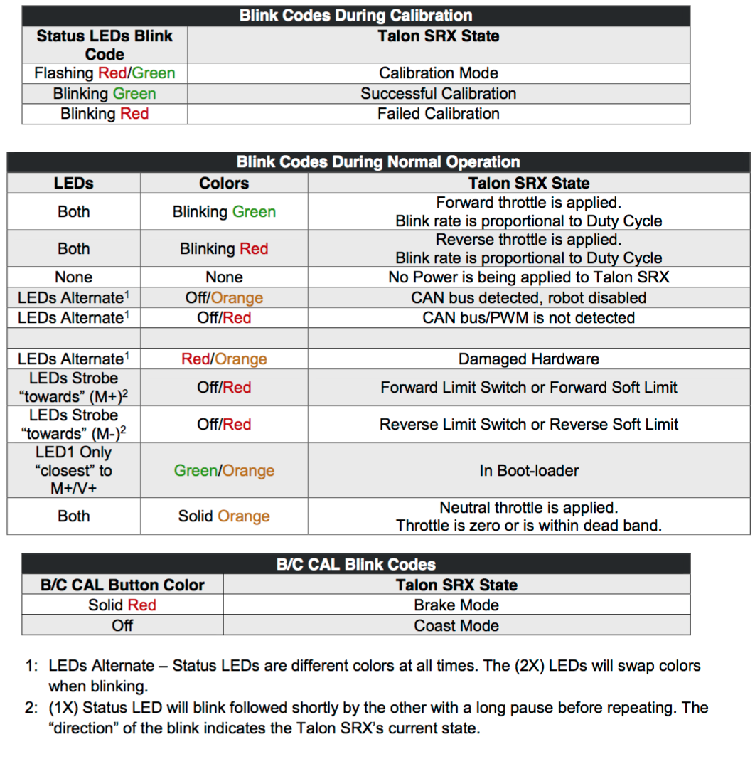
Understanding Blink Codes
See Talon Users Guide Blink Codes, section 2.3
Talon is behaving erratically...
Make sure no two Talons are configured to use the same device ID. Use roboRIO Web-based Configuration page to review Talons' device IDs.
Flakey communications are often due to mis-addressed CAN devices. Check for duplicates, and make sure everything is connected where it should be.
Device ID conflict (all Talon SRXs blinking red)
If there is a single CAN error frame, you can expect all Talon SRXs on the bus to synchronously blink red. This means two or more “common ID” Talon SRXs are periodically attempting to transmit using the same CAN arbitration ID, and are stepping on each other’s frame. This causes an intermittent error frame which then reveals itself when all Talon SRXs blink red.
Encoders doesn't reset
There is a delay in resetting encoders. Software needs to take into account for this delay.
Can't read feedback device status
Not all sensor types support the ability to read feedback device status isSensorPresent(). The supported sensor types are: CTRE Mag Encoder, Pulse-Width Encoded. All other signals will return FeedbackStatusUnknown.
Encoders oppositive of the motor direction
reverseSensor() to keep sensor and motor in phase for proper limit switch and closed loop functionality.
Multiple Talons and a Single Sensor
There are many uses where a mechanism requires multiple Talon SRXs but a single sensor. For example, a single-side of a tank-drive or a shooter-wheel powered by two motors. The recommended strategy for these mechanisms is to...
- Connect the sensor to one of the Talons. This Talon will be referred to the “master” T alon.
- Set the supplemental Talon(s) to slave/follower mode and follow the device ID of the “master” Talon. See Section 9.1 for details.
- Select PercentVoltage Mode on the “master” Talon. Write a test robot application to drive the “master” Talon manually and confirm all slave Talon(s) correctly follow by watching the LEDs on all involved Talon SRXs. This can be done without motors connected. Consult Talon User’s Guide to avoid damaging Talons by incorrectly wiring inputs/outputs.
- Next, connect the motors to all involved Talons. Consult Talon User’s Guide to avoid damaging Talons by incorrectly wiring inputs/outputs. Test to make sure all motors drive in the correct directions. For example, when drive a shooter wheel, the motors may be oriented to require each motor to drive in opposite directions. If this is the case signal the slave Talon to reverse its output (Section 9.1.4). Do not use excessive motor output. Otherwise you may stall your motors if the slave and master Talon are driving against each other.
- Instrument the Sensor Position or Velocity using the roboRIO Web-based Configuration Page Self-Test, or print/plot the values. Ensure that sensor moves in a positive direction when master Talon is given positive forward throttle (green LEDs).
- Now that the motor(s) and sensor orientation has been confirmed, select the desired control mode of the master Talon. Any of the closed-loop/motion-profile control modes can be used.
- When using Velocity Closed-Loop, Current Closed-Loop, or MotionProfile Control Mode, be sure to calculate the F gain when all slave Talon/motors are connected and used.
CAN Bus Utilization/Errors Metrics
See CAN bus Utilization/Error metrics section in the (programmer's manual)(http://www.ctr-electronics.com/Talon%20SRX%20Software%20Reference%20Manual.pdf).
The driver station provides various CAN bus metrics under the “lightning bolt” tab. Utilization is the percent of bus time that is in use relative to the total bandwidth available of the 1Mbps Dual Wire CAN bus. So at 100% there is no idle bus time (no time between frames on the CAN bus).
When starting out with the FRC control system and Talon SRXs, it is recommend to watch how these CAN metrics change when CAN bus is disconnected from the roboRIO and other CAN devices to learn what to expect when there is a harness or a termination resistor issue. Determining hardware related vs software related issues is key to being successful when using a large number of CAN devices.
Is there any harm in creating a software Talon SRX for a device ID that’s not on the CAN bus? Will removing a Talon SRX from the CAN bus adversely affect other CAN devices?
No! Attempting to communicate with a Talon SRX that is not present will not harm the communication with other CAN nodes. The communication strategy is very different than previously support CAN devices, and this use case was in mind when it was designed. Creating more Talon software objects (LabVIEW Motor Open, or C++/Java class instances) will increase the bus utilization since it means sending more frames, however this should not adversely affect robot behavior so long as the bus utilization is reasonable. However the resulted error messages in the DS may be a distraction so when permanently removing a Talon SRX from the CAN bus, it is helpful to synchronously remove it from the robot software.
Analog Position seems to be stuck around ~100 units?
When the analog input is left unconnected, it will hover around 100 units. If an analog sensor has been wired, most likely it’s connected to the wrong pin.